AJAX Hopper Design for Reliable Discharge of Bulk Solids
The design of hoppers of simple form, such as conical or plane vee construction, is well established based since the 1960s when Dr Andrew Jenike developed a complete methodology for flow of bulk solids that encompassed:
- Test equipment and procedure for measuring parameters relevant for flow
- A means of characterising the flowability of the bulk solid
- A theory of solids flow including definitions of mass flow and core flow
- Identifying impediments to flow such as a stable arch (or dome) and a rat hole
- A flow-no flow rule
- Design basis for hoppers and silos which predicted outlet sizes and wall shapes/slopes for mass flow
The first and most important feature to be established in the initial assessment of a hopper storage system is whether the material is free-flowing in all the conditions of material supply and the long-term operating procedures which may apply. In general, all cohesive materials and those which settle or compact to a density which depends upon the stress history of the product will be of uncertain flow behaviour. Similarly, bulk materials which contain some free surface moisture or other substances favouring particle adherence, those which are liable to incur particle surface changes due to chemical or thermal effects, such as crystal bonding or surface fusion, and operating conditions whereby condensation or liquor contamination may occur may all give rise to poor flow states of the material. Other bulk materials which shed fines on impact, shear or surface clip, or which segregates readily to give regions of fine particles, can also lead to difficult flow situations in materials which appear to be free-flowing in their normal loose condition. These above effects may be aggravated by extended times of storage at rest or by sustained operating circumstances.
Without reliable prior experience of like materials and operating conditions, and with equipment of the type and scale as the application under consideration, a thorough design process should be followed to establish the minimum hopper outlet orifice dimensions and the hopper form which will permit reliable flow to take place. The next key decision is whether the contents are required to discharge in a mass flow pattern or whether material in some zones of the hopper may remain stationary during some phase of the discharge process (non-mass-flow). Mass flow essentially requires the total contents of the hopper to move at any time, with the material being discharged with slip taking place on all wall contact surfaces, even though there may be substantial variations in the flow velocities in different regions.
With non-mass-flow regimes, material may draw down a central region of the hopper, with the surface layers draining into the flow channel (core flow). In this mode, there is virtually no slip on the wall contact surfaces. Another variant is where steep walls in the lower section of the hopper give local mass flow, whilst in the higher storage regions, the side walls are less steep and no wall slip takes place to give a pattern of discharge termed “expanded flow”.
The above forms of flow generally have a fully live movement of material in the cross section of the hopper outlet during discharge. In some cases, and particularly with extended forms of hopper outlets, flow may take place in some regions of the outlet, but not in others, according to the pattern of extraction of the outlet mechanism (or due to a partly open control valve). Many other non-mass-flow variants are caused by asymmetrical geometry of the storage container, such as gullies, eccentric construction and the like.
Clearly, to enable mass flow to develop in a hopper, the full interface region with the discharging apparatus must exhibit “live flow” during all periods of extraction. Features of duty, properties of the material handled, process needs, economics and site particulars may all influence the choice of an optimum flow contour appropriate to a specific application.
Powder Tests
AJAX routinely measures Wall Friction properties which are of wide value with respect to the design of hoppers, chutes, flow channels and discharging devices. The results will show the static and dynamic slip properties on contact surfaces, including the angle of friction, surface cohesion and any tendency for the material to stick-slip when sliding on boundary surfaces.
The ability of the stored bulk solid to arch over the outlet or create a stable rat hole is probably the most pernicious feature when bulk solids are stored in a hopper that identifies this as an area that deserves attention. It would appear however that most effort in silo design has been directed to achieving storage capacity and matching the outlet size to the means of offloading. Consequently many hoppers under-perform - discharge is not possible without intervention, output is insufficient, incomplete or not in the condition required. This indicates that the simple questions of what outlet size and wall slope is needed to get the reliable performance that industry needs, are not being properly addressed. This is where shear strength tests come in to their own and help predict a size for reliable follow.
Hopper Types
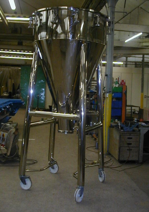
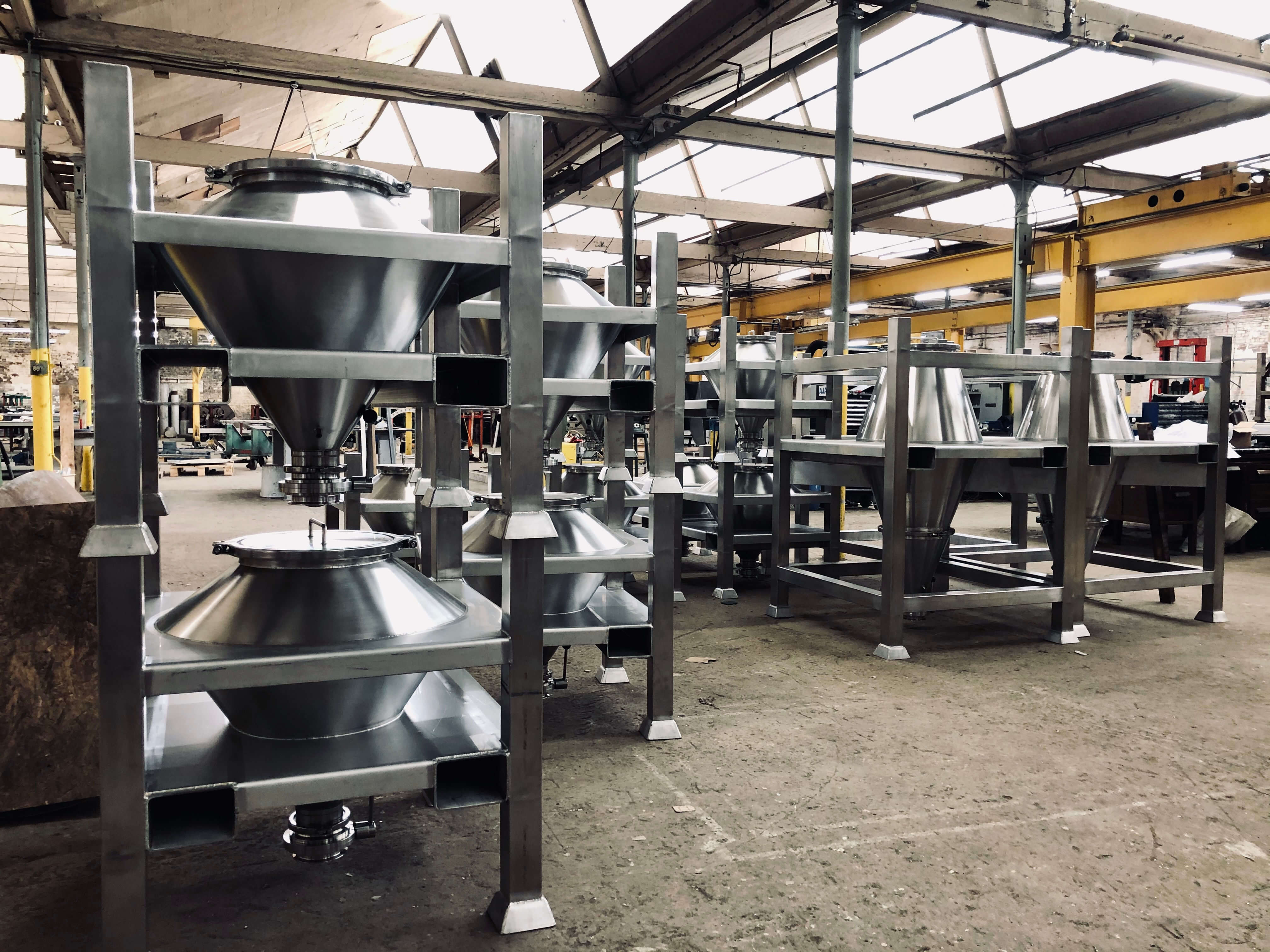
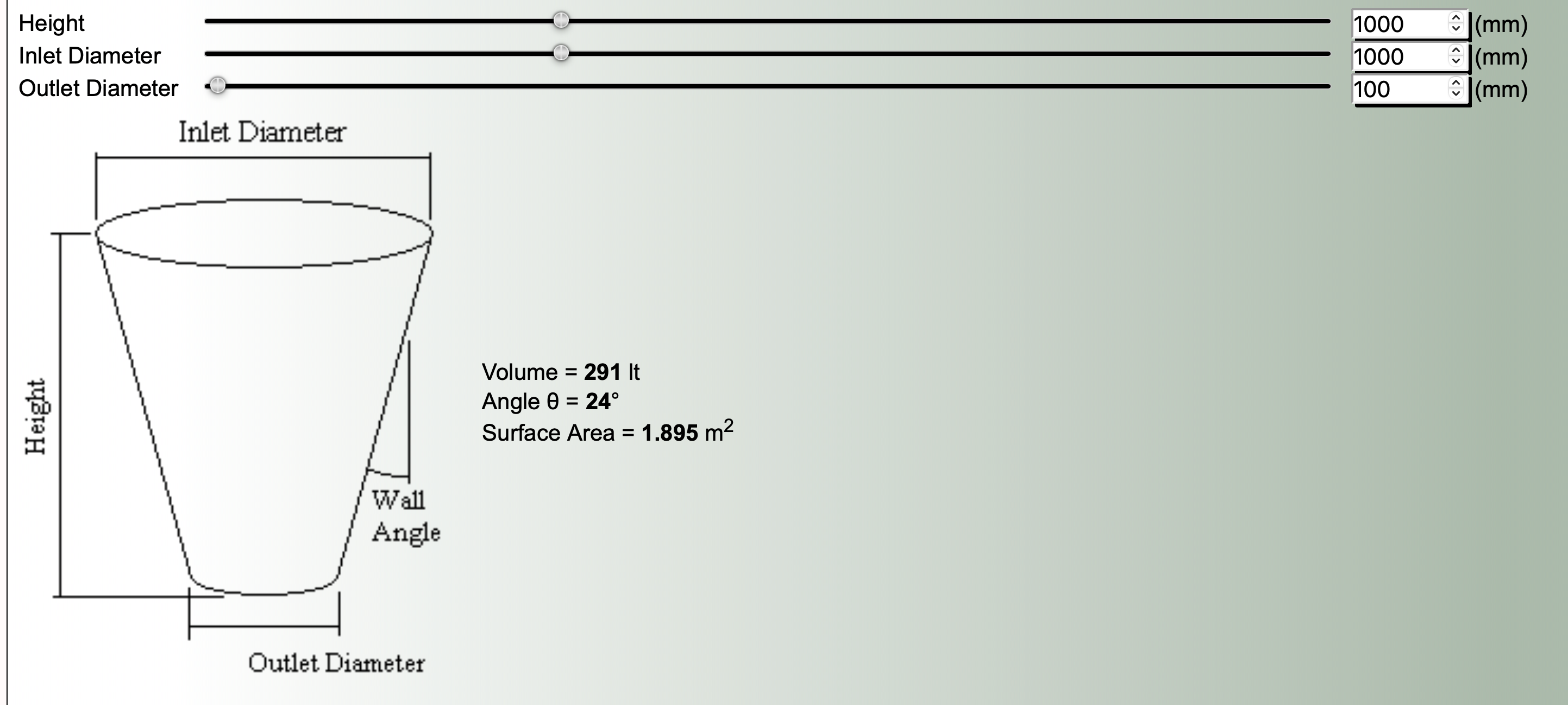
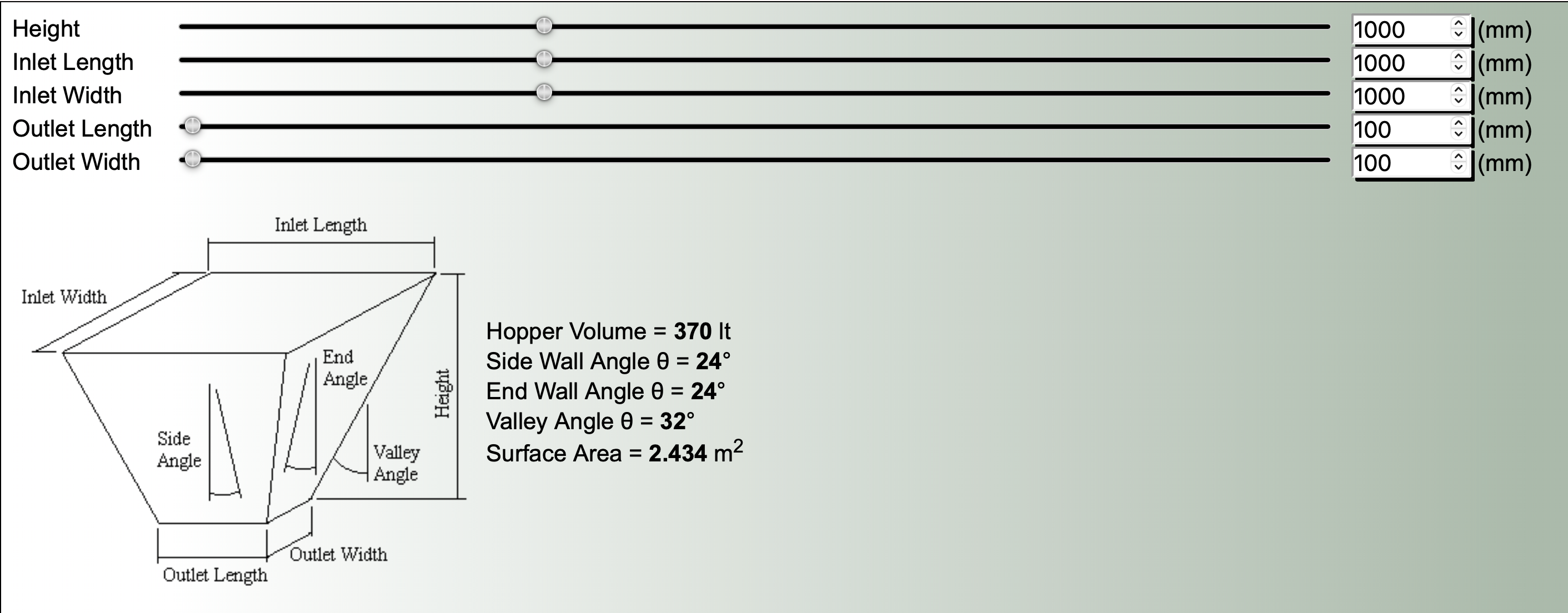
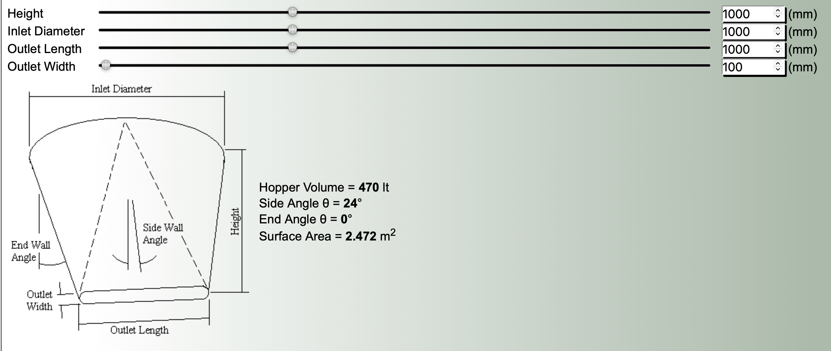
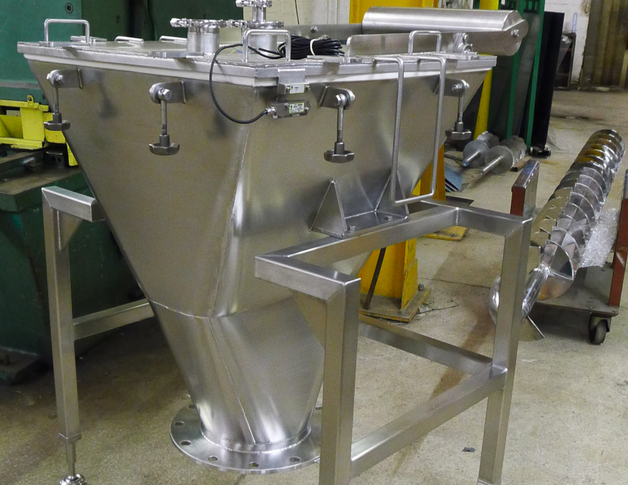
Storage vessels for bulk solids come in a wide range of shapes and sizes and with a variety of names, eg bins, bunkers, tanks, silos and hoppers with the preference usually dependent upon what industry and where in the world the storage vessel is located (Rotter, 2001). In this work the primary preference shall be for the term hopper. The word hopper is sometimes linked with small scale storage and is used to describe the converging section of a storage vessel, however far from being restrictive these are aspects which apply in many of the storage systems which suffer problems of arching or rat holing. Whilst the scale of some installations can be up to 10,000 tonnes (Haaker, 1983) very many are used in plant where it is common for the hopper to hold less than 100 tonnes with many between one and 10 tonnes. It is clear therefore that a wide range of designs will be possible; examples of the some of the most common shapes are given below with links to volume calculation programs.
Hopper Volume Calculations
See Also
Twenty Ajax Hoppers for Liberty Powder Metals
Ajax Mobile Hopper for Pharmaceutical Production
Key Steps for Hopper Design
Hopper Inserts
Hopper and Feeder Interface
Powder Testing for Flow
